This week (5 December) the cooldown of the Cryogenic Distribution System (CDS) started in the ESS accelerator tunnel.
This activity is an important part of the commissioning of the ESS accelerator, leading to the installation of cryomodules in the superconducting linac this coming spring.
The cooldown of the CDS started on Monday 5 December.
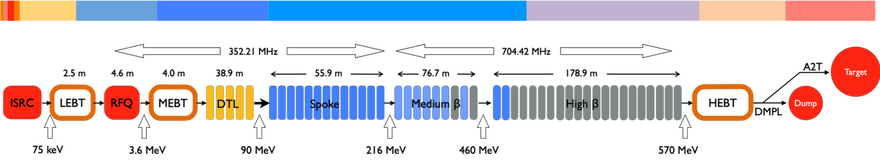
The CDS delivers cooling power to the cryomodules. They are part of the super-conducting portion of the accelerator (the "cold" part), where the proton beam is accelerated by means of electric fields in superconducting cavities within the cryomodules. In order to achieve super-conduction, the niobium cavities must be brought to extremely low temperatures.
As shown in the accelerator layout image, from the superconducting portion of the linac, the proton beam is then transported via the high energy beam transport (HEBT) to the target station.
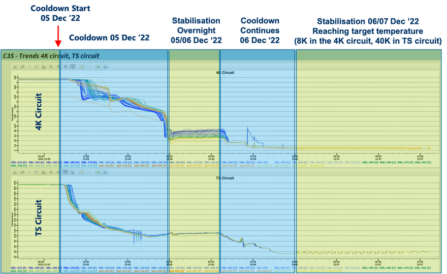
This CDS cooldown is a complex activity and a large team effort of the Cryogenics team, ICS and the Operations team. In less than 1.5 days the temperature in the CDS was reduced below 70K, below which no further mechanical stresses on the system are to be expected. Permanent helium leakage measurements and a tunnel inspection on Tuesday morning were conducted with satisfactory results. The rest of the week will be spent on thermalisation, controls debugging and optimisation before heat load measurements will take place.
An important milestone
Commissioning of the CDS is critical to maintain the schedule for the main milestone for the Accelerator sub-project: RBOT (Ready for Beam on Target).
Only once the CDS is fully commissioned, the installation of cryomodules in the tunnel can start.
Successful commissioning of the cryogenic distribution system is a key step in getting the superconducting linac operational.
What happens next?
The cooldown is carried out 5-9 December, after which the tunnel will be opened for access again, to allow for the installation of Drift Tube Linac 2 (DTL2), the Faraday cup for DTL4 and the reconstruction of the temporary shielding wall separating the Normal Conducting Linac from the Superconducting Linac.
Cold compressor tests involving the ACCP Accelerator Cryogenic Plant (ACCP) will resume in January, with further cooldown tests and heat load measurements to be conducted before the planned warm-up in February 2023.
Successful commissioning of the CDS will be followed by the start of cryomodule installation.
Cryogenic Distribution System
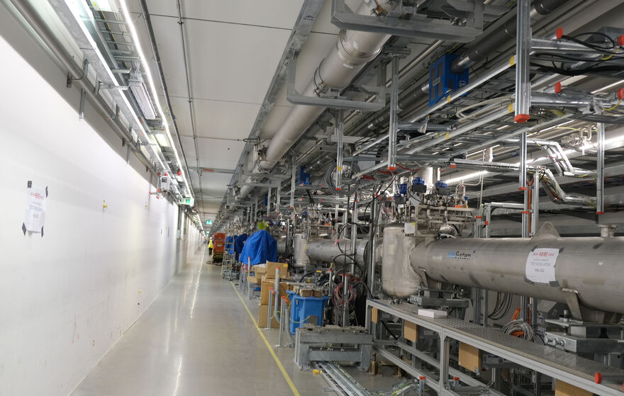
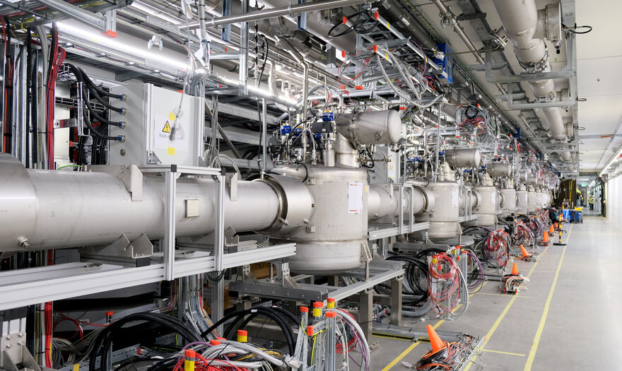
The Cryogenic Distribution System (CDS) for the ESS linac delivers the cooling power from the Accelerator Cryogenic Plant (ACCP) to the cryomodules by means of a flow of supercritical helium at 4.5 K and 3 bar(a).
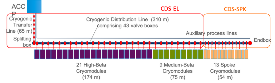
It consists of a carefully insulated piping system inside a vacuum jacket to ensure minimal heat load on the piping in order to keep the helium very cold. The system distributes the helium through a set of valve boxes, connected to each of the 43 cryomodules. Inside the elliptical cavity cryomodules the required 2 K is obtained with the help of a heat exchanger and a Joule-Thomson valve. In the spoke section the heat exchanger and JT valve are placed in the valve boxes where the 2 K helium is produced and transferred to the cryomodule via a jumper connection.
The valving system enables the individual control of the flow and temperature of the helium into the cryomodules, so that it matches exactly the right cooling capacity of the cryomodules.
The CDS also distributes helium at around 40K to cool down, and hence improve the thermodynamic efficiency of, the thermal shields of both the cryomodules and the CDS itself.
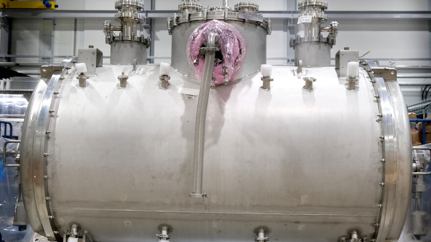
Cryomodules
A cryomodule is a vacuum-jacketed, insulated structure, that contains a series of accelerating cavities arranged sequentially. The ESS accelerator operates on the principal of adding small amounts of energy, relatively speaking, multiple times to the particle beam. This is done by having accelerating gaps with strong electric fields, and the cryomodules are part of the overall accelerating structure. They operate at 2 degrees above absolute zero (2K), enabling the niobium inside to have no electrical resistance, which then makes the accelerating structure very efficient, from an energy consumption perspective.
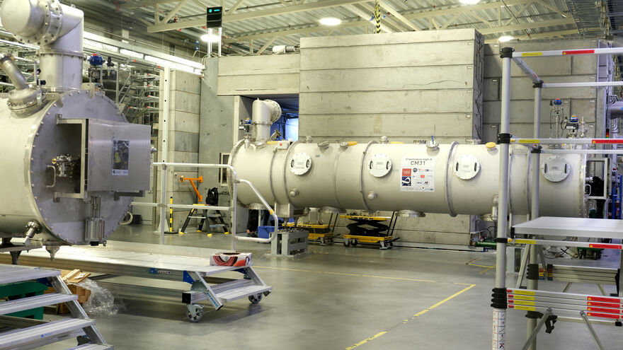
For the medium beta and high beta elliptical cryomodules, there are four cavity strings arranged one after the other, each of which has its own radio frequency energy supply, and those four cavity strings are contained within a common physical envelope that then connects to the valve box of the cryogenic distribution system.
Radio-Frequency (RF) power is supplied from the power sources in the Gallery building via waveguides. Each RF cell on the Gallery-side is equipped with two modulators and eight klystrons – one for each cryomodule cavity string.
The spoke cavity cryomodules have two cavity structures, each fed by a tetrode-based radio-frequency power station in the Gallery.