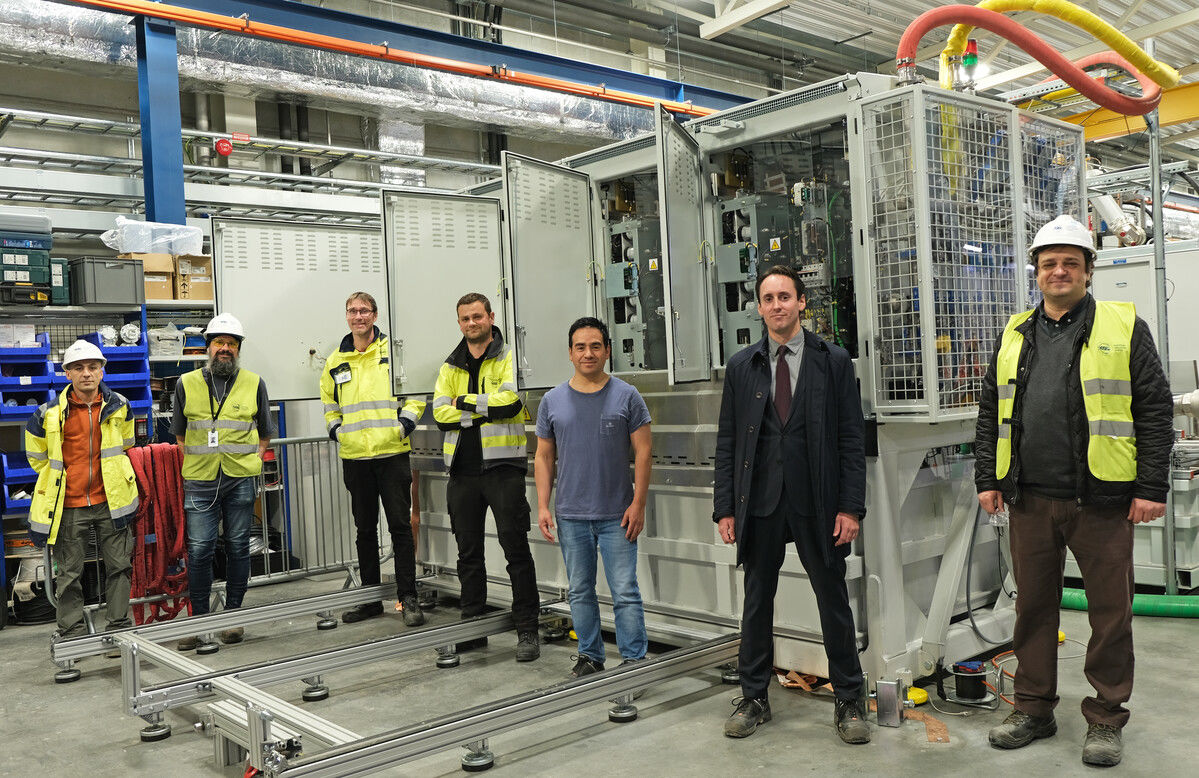
ESS in collaboration with Lund University researchers, and together with ESS Spanish In-Kind Partner, ESS Bilbao, and supplier, Jema Energy, have produced a high-voltage modulator that signifies a paradigm shift for the power supply of linear particle accelerators worldwide.
When ESS is in full operation, it will be the world’s most powerful superconducting linear accelerator, providing neutron beams that are about 100 times brighter than what is produced today from reactor-based neutron sources.
Most accelerators are powered by a standard chain of components - you plug it in, then AC power from the electricity grid feeds a specialised, but mostly standard, power converter: the modulator.
The modulator is basically a giant adaptor that takes power from the electricity grid and feeds it to klystrons. If you consider the amount of energy needed to power a linac, and that protons are produced in pulses, it is very important to have a device that can take very large amounts of electricity from the grid without causing any flicker on the electrical grid in Lund or South Sweden.
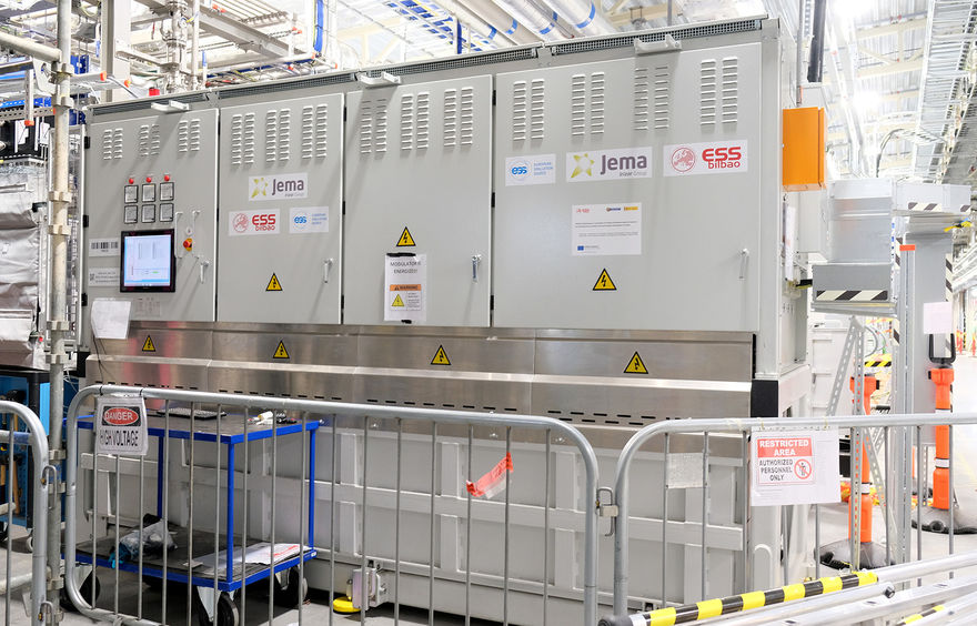
These twelve ton, specialised components comprise a set of power electronic devices and control software, usually housed in a metallic cabinet about the size of a compact car, which regulates the power supply to klystrons.
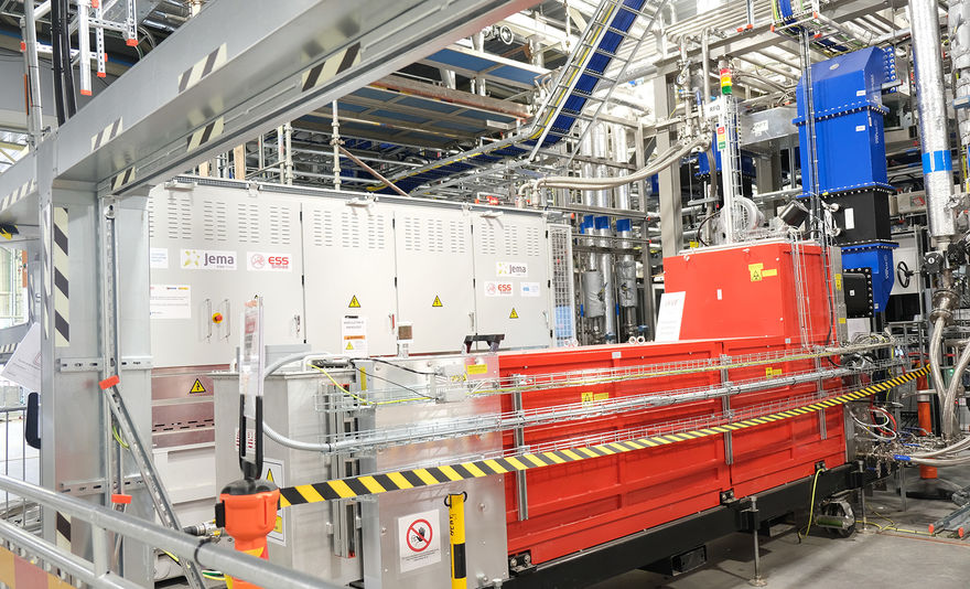
Klystrons have the task of providing the power that accelerates the proton beam towards the Target. It does this by converting about half of this power into electromagnetic waves, or Radio Frequency (RF) power. .
The RF power is fed to both the room temperature and super-cooled vacuum cavities through which the accelerator’s proton beam is travelling. The RF waves are converted to finely tuned electromagnetic fields inside these metal cavities, accelerating the beam to ever faster speeds. These technologies have been around for decades, powering accelerators around the world..
The ESS Accelerator, however, is a game-changer – its 5 MW power specification makes it five times more powerful than the Spallation Neutron Source in the US, which is the most recently constructed large-scale spallation source in the world. It was suspected by ESS early on that traditional modulator technology would be brought to its limits. Testing would be necessary, and ESS and CERN began to work together back in 2010 to determine if the possible was indeed optimal.
The Challenge
One of the unique characteristics of ESS is that neutrons are not delivered continuously to an experiment but rather in discreet sets of 2.86-millisecond “long pulses”. The instruments at ESS are designed to take advantage of this timing, and the reliability of the beam’s characteristics is critical to the innovative time-resolved experiments that will be performed at ESS.

The delivery of this long pulse relies on the power supply. The proton beam, the RF power, the resonating cavities, the rotating target wheel, the neutron beams and the pulse-shaping choppers for instruments are all synchronised relative to the 14-shots-per-second repetition rate of the beam pulse –14 Hz will be the heart rate for the entire facility. A clean, consistent, and reliable burst of electrical power must be supplied by the modulator at precisely this rate.
The modulator does not continuously dump out the required power to keep the Accelerator functioning, it must do so for exactly the right period of time, about 3.5 milliseconds and in synchronsation with all other beam accelerating systems. To do this, it must start and stop the power feed as sharply as possible, with 69 milliseconds to recharge before the next surge.
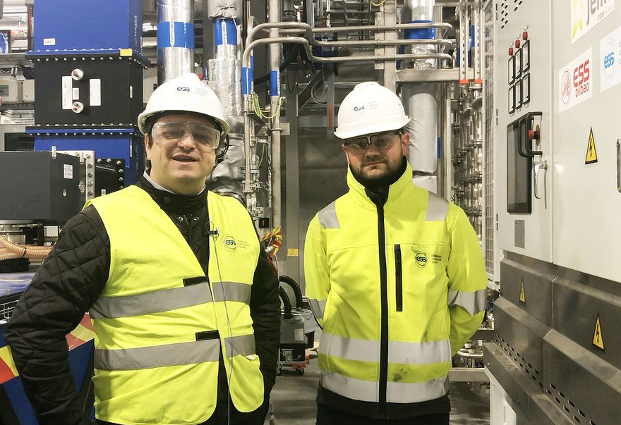
“We have found our system to be very stable and precise, therefore generating very high quality pulses that can be described by low pulse rise times (below 130 microseconds) and high pulse flat-top accuracy and stability (better than 0.15%),” reveals Carlos Martins, “And we have experimental results – data from the test stand as well as from RF operations tests on site that confirms this.”
Another important fact explains Martins is, “we aim to obtain a constant power absorption from the grid. It is like we are flipping this light switch on and off 14 times a second. But this is not a light bulb. This is like 115,000 100-watt bulbs for each modulator. We have 33 modulators – 3.8 million bulbs - 380 megawatts of switched power!”
A Plug & Play machine
Machines like these which absorb very large amounts of power from the grid can cause a power disturbance on the grid, so traditionally, one needs to have external compensation to counter the fluctuations these machines can create.
“The ESS-designed modulator has an integrated system which basically provides internal line power regulation inside the device. This is called an Active Front End, which takes care of the power quality to secure that there will be no flicker on the grid,” explains Martins.
“The active front end is a fast fully controllable power converter unit synchronised with the different subsequent internal stages and the incoming AC power line– it takes what it needs on a constant power flow with very minimal distortion on the feeding grid.” This issue is called “power quality, according to Martins, and the resulting power and current absorption from the grid that we obtain are then very “pure and of a very high quality".
“This is the first time in the world using an Active Front End on a modulator,” Martins beams, explaining that most of previous-generation modulators require some type of external compensators to deal with issues like distortion and instabilities, which would have to be placed on the electrical grid.
“There is no electrical network in the world that would allow us to take 380 MW pulsed power with these characteristics: 3.5 ms, 14 shots per second,” explains Martins. “All the network in Lund, in Sweden, even across Europe would be flickering up and down and that would not be acceptable. So, we needed somehow some filtering internal to ESS power network and the best place where they should be are inside the modulators to cancel the disturbances as close as possible to their source.
One also needs to ensure that the quality of the High Voltage pulses delivered by the modulators to the klystrons meets the unprecedented requirements of ESS accelerator. As such, the pulse rise time (i.e. the time necessary to switch the output voltage from zero to 99% of full voltage, 115kV) shall be as short as possible in order to maximise system efficiency, therefore contributing to one of the ESS core values (sustainability). Furthermore, the pulse flat-top precision and reproducibility must be as high as possibly feasible in order to ensure low radioactive losses in the accelerator.
Start of RF Operations
The first modulators are today already installed in their permanent places in the Klystron gallery, and have been tested with full klystron power, signaling the start of RF operations at ESS.
According to the ESS Power converter’s team, the initial results of the full-scale unit are impressive and some are exceeding the initial specifications:- the pulse quality, which is one of the most important specification, reveals a flat-top precision and reproducibility about two times better than required; the maximum energy released to the klystrons in case of a gun arc is 40% below the specification; the electrical grid power quality main parameters (i.e. flicker, current harmonic distortion) are also about 40% and 80%, respectively, better than the specified ones.
When all the modulators are installed - a total of 17 modulators are ready to support phase one of the initial operations allowing for beam acceleration with an average power on the target of 2MW. This operation scenario is expected to allow for science production at ESS until end 2025
To proceed to 5 MW operation, a further set of 16 modulators shall be purchased, tested and installed. This will be based on a “copy-paste” of the first modulators but with a few considerations on single source components and alternatives to these in order to ensure availability of multiple suppliers of critical components all along the system’s lifetime.
InnovativeFutures – Possible Next Steps
The ESS modulator is a good candidate for innovation considerations, both on knowledge and technology transfer. ESS has created something both unique and powerful which could then be applied at other facilities – they could use similar technology and modulator design methodologies and techniques to make the most of the great benefits the ESS modulators offer.
Sharing knowledge gained during the development of some of the pioneering solutions being developed during the ESS project where the modulators are but one example, could also be of benefit to scientific R&D projects in Industry or in other Big Science facilities where they may be able to apply this knowledge, and learn from challenges and opportunities ESS has faced, Martins explains. “We are always happy to share knowedge that can help advance science for future generations. This helps make R&D reusable and sciencemore sustainable!” he adds.

The concept of an active front end housed inside the machine could also be very significant. “There is the possibility that our modulator device can be repurposed to inject power back into the grid,” continues Martins. “Renewable energy is an important topic for a sustainable future and one could undertake a possible feasibility study of using the modulators to receive solar power from photo voltaic panels and redirect it to the klystrons, therefore contributing partially to the accelerator powering when needed and reducing the power consumption from the electrical grid; or to power other parts of ESS via the distribution network, sending excess energy back to the grid whenever the accelerator is in shut down or operating in low power testing modes.
This would constitute the ultimate proof of sustainability for ESS, where the accelerator would directly be powered into a great extent (up-to 20 or 30%) from local renewable sources. Many new things are possible with modern power electronics,” smiles Martins.
SUMMARY OF WHAT MAKES THE ESS MODULATORS SO SPECIAL
- Better pulse quality: Improved quality of high voltage pulse delivered to klystrons, with improved power efficiency.
- Use of Active Front End – internal power regulators that secure a constant power supply without any flicker or harmonic distortion on the electricity grid, ensuring high power quality consumption.
- Compact design: Space saving – previous generations of modulators, like the one installed in ESS Test Stand 2, have been known to take up about twice of space for the same power ratings.
- Plug & play solution: Everything is contained in a single box. At other facilities they may need 3 separate cabinets to house all the parts. This modulator can be transported as a single block by rolling it on its own wheels and just needs to be plugged into a socket and then connected to the klystrons.
- Modular concept: Allows for the utilisation of “standard of the shelf” power components, easier to source from the market. Facilitates maintenance. Allows for the increase of rated power by adapting the number of modules one installs. Up to 660 kVA average power possible, allowing the supply of 4 x 1.4MW klystrons in parallel per modulator unit.
- Lower cost due to limited component count and the usage of standard LV components into a great extent. Fewer modulators needed for the project (33 in case of ESS). More than 20M€ of savings for the ESS accelerator when comparing to best alternative.
- Mechanical design: Active power electronic stacks, most sensitive, are located on the most accessible areas of the cabinet. No active power electronic devices inside oil tanks; only the passive high voltage stage is placed in the tank which facilitates maintenance and repair, making it more user-friendly. A specially designed tank extraction system based on railways allows for quick and easy extraction/insertion of the 3 ton tank with minimum. These features reduce the effort and downtime involved for maintenance or repairs.
- Compatible both with PULSED and CW (Continuous Wave) operations and with different types of RF amplifiers (Klystrons, IOT’s, tetrodes, etc.);
-
Safety and reliability: Rugged cabinet enclosure to absorb the shockwaves resulting from any possible internal short circuit or capacitor bank explosions; utilisation of three seperated capacitor banks instead of a single one to reduce, by 66%, the energy resleased in case of short curcuits across one of them, Sealed High Voltage oil tank with integrated double container (i.e. oil leakage retention bin); Safety PLC (Programmable Logic Controller) to autonomously handle all personal safety protections; redundancy mechanism for interlocks allowing for safe protection even in case of some sensor failures; Conservative design and selection of all power components; Selection of well proven and qualified sub-contractors.